- 2024-01-07: Publication v1.0
- 2024-04-19: Added details about CAN interface of new data logger
Data Logger Specification
FSCzech is testing a new data logger with advanced features to be on par with the newest cars, including DV. There will be a limited number of beta units for use. The organizer reserves the right to choose whether the team receives a Legacy data logger or a Next generation data logger (beta).
Legacy Data Logger
Entire data logger has to be put into the TS enclosure with only the USB cable going out. Ensure sufficient USB cable separation from non-insulated TS components inside the enclosure, due to the USB cable not having a maximum TS voltage rating. Refer to EV 4.5, mainly EV 4.5.2. The provided cable has to be returned to its original state. 1 m of data cable with USB A connector has to be available from outside of the car. The team is allowed to use multiple cables and connect the external part of the cable on demand.
Drawings
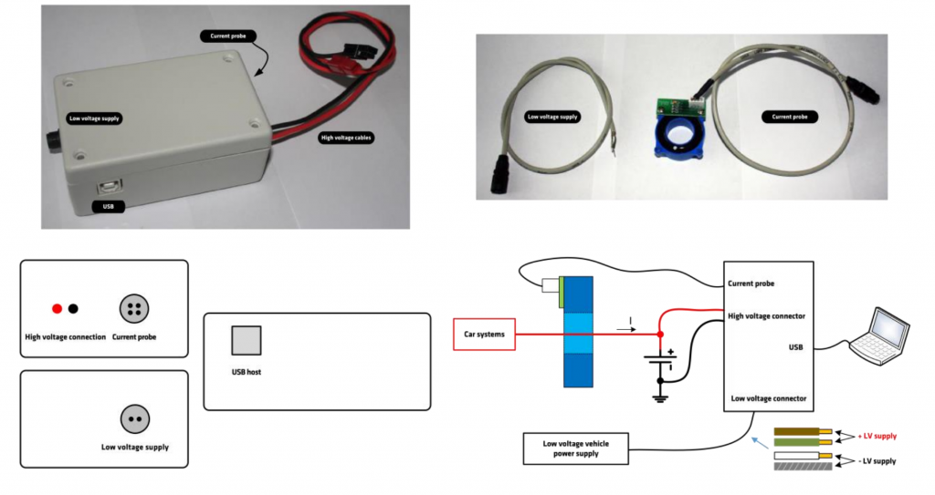
Technical Data
- Wired data export connection by USB (B-A) cable. (provided by organizer)
- Low voltage supply harness will be provided by the organizer. Minimum length 50 cm.
- Supply voltage between 9 V and 36 V
- Maximum current draw: 100 mA (typ. less than 50mA)
- High voltage sensing connectors: Anderson Power 1327 PP15, black (TS-) and red (TS+)
- Matching connectors are provided by the organizer. The team is responsible for connector crimping.
- You can find the 3D model on our website: fsczech.cz/documents-2024
- The serial number of the main unit must match the correct current probe.
- The orientation of the current must be wired according to the basic connection diagram.
Next Generation Data Logger (BETA)
Entire data logger has to be put into the TS enclosure. TS enclosure with data logger can’t be shielded to ensure wireless connectivity.
CAN interface
- Supports automatic baudrate. Any node on the bus has to send any CAN message at least until data logger starts sending it’s ow periodic message (baudrate lock).
- Supported baudrates: 125 kbit/s, 250 kbit/s, 500 kbit/s, 1Mbit/s
- Logs team generated messages according to FSG 2024 handbook v1.1, and RES messages
Periodic report message
- MAY CHANGE!
- Standard ID 0x7F0
- 10 to 50 Hz
- Payload, LSbyte first + LSbit first notation, little endian integers, DLC = 8 bytes
- TS voltage, unsigned integer 16 bits, 0.01 V step
- TS current, signed integer 16 bits, 0.01 A step
- TS power (after moving average – D9.4.1), signed integer 16 bits, 5 W step
- overflowing “up-counter”, increments on every message transmit, unsigned integer 4 bits
- Memory used, unsigned integer 4 bits
- “Over-power” flag, set at OP event (D 9.4.1) and remains set for another 500 ms, bool 1 bit
- POR flag, transitions 0->1 after 5 s since boot-up, bool 1 bit
- reserved, 6 bits
Drawings
- You can find the datasheet on our website: fsczech.cz/documents-2024
Technical data
- Wireless data connection (2.4 GHz).
- Low voltage connector (power + CAN)
- Harness will be provided by the organizer. Minimum length 50 cm.
- Connector:
- housing: molex 33472-4001
- terminals: molex 33012-2002
- pinout: 1 LV+, 2 LV-, 3 CAN-H, 4 CAN-L, (CAN relative to LV-)
- Supply voltage between 9 V and 36 V
- Maximum current draw TBD A
- Bolted high current path terminals. Refer to drawings for dimensions. The team is responsible for appropriate fasteners.
- High voltage sensing terminal: AMPHENOL ANYTEK HB0101800000G